About 1-10V illumination control
ProfiLux controllers have the ability to control any 1-10V compatible lighting fixture. With the correct cables and accessories, any dimmable lighting fixture that comes with its own 1-10v interface can be dimmed and controlled according to the light schedule you create.
The steps below will show you how to create a dimmable light schedule using the Illumination function.
Before you begin
- If you are not familiar yet with the operating concept of the ProfiLux Controller, we highly recommend to first read the Knowledgebase Article “How the ProfiLux Controller works“. It gives you an understanding of the basics and the operational concept of the controller
- Make sure you have all the correct parts on-hand. (See also list below)
Choose one specific to your needs…
| (Accessory) | (Purpose) |
| S-Port & L-Port breakout box (PL-1680) | For controlling lights that include a 1-10v control port |
| LEDControl4 V2 (PL-0974) | For controlling lights that are dimmed through a PWM signal |
| Mitras Simu Driver (PL-0987) | For controlling Mitras-Simu-Sticks |
A single 1-10v port can control 2 independent 1-10v channels
Each 1-10v (Yellow) L-channel port on the ProfiLux, expansion cards and expansion box are capable of controlling 2 separate 1-10v channels.
Connect your 1-10v control cable to the ProfiLux
- Take the 1-10V control cable and connect it to your lighting fixture and GHL accessory
- Connect the GHL accessory to an available YELLOW L-channel port on the ProfiLux
If you have any of the GHL accessories below, please make sure to follow the initial programming steps as noted below. These accessories must first be connected to L1 – L6 ports for initial programming. Once that is completed, you can connect this device to any L-channel port.
- LEDControl4 models
- Mitras-Simu-Driver
- ProfiLux-Simu-LEDs
Initial programming for select GHL accessories
If you have any of the above items, go to the 1-10V Interfaces settings page (press Menu icon), press Program Devices, then select the device you have and follow the on-screen steps. Once completed, disconnect the accessory and connect it to the desired L-channel port, then proceed to the next step below.

Assign 1-10V channel to an Illumination channel
- Press the Menu icon and select 1-10V interfaces
- Select the 1-10V interface number where you have the light connected
For example, if you connected one control cable directly to port L1 / L2, you should choose 1-10V interface #1. If you are controlling two channels and both are connected to L1 / L2 via a YL2-splitter, you should choose interface #1 and #2.
3. Set the function to Illumination and select the channel number to assign to this light, then press SAVE
Since most LED fixtures include more than 1 channel, we recommend assigning each to its own ILLUMINATION channel for independent control. For example, a Royal Blue LED channel can be on Illumination 1 and White LED channel can be on Illumination 2.
4. Repeat steps 2 and 3 for each lighting channel that needs to be assigned


Create a dimmable light schedule
- Press the back-arrow, press the Menu icon, select Illumination, select Illumination channels
- Select the illumination channel you assigned earlier
For example, if you assigned the L1-channel to Illumination 1, select Illumination 1. If you assigned L2 to Illu.2, select Illumination 2.
3. Enable the DIMMABLE option (as shown)
4. Type-in a description; Royal blue LED
5. Press ADD, specify the time and percentage light output for this time, then press ADD
Repeat step 5 and continue creating NEW time-points until you are satisfied with your schedule. Press SAVE when done.
Pressing the Chart tab will show you the complete schedule.


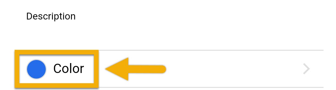
Color code your Illumination channels
If you’d like to give each Illumination channel a specific color, you can do so here. Make sure to press SAVE after the color is selected.
Optional: Setup Temperature Dependent Light Reduction
ProfiLux 4 / 4e can provide an additional layer of temperature management safety when you use the Temperature Dependent Light Reduction feature. If your tank temperature rises higher than a max allowed temperature, the ProfiLux will reduce the light output of specific lights.
1. Go to the Illumination channels page, select your light channel and enable Temperature-dependent light reduction (as shown), then press SAVE
![]()
If you want multiple illumination channels to react to this feature, repeat this step for those channels.
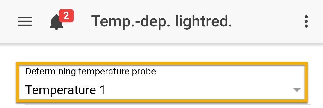
2. Press the back-arrow, press the Menu icon, select Temp.-dep.lightred.
3. Select the temperature probe that will be responsible for controlling the assigned Illumination channel(s).
4. Specify at what temperature the brightness of your dimmable light should be reduced and when it should be switched off completely, then press SAVE.
For example, if the target temperature of your temperature sensor is set to 77°F, the min. temperature excess is set to 3°F and the max. temperature excess is set to 6°F, the brightness of the assigned lighting channels is reduced from 80°F and when it reaches 83°F and above, they are completely switched off.
Alternate method via ProfiLux touch keys
If you wish to bypass GHL Connect, you can also create a dimmable light schedule by following these steps:
Assign 1-10v channel to an Illumination channel
- Press the up or down arrow key
- Select System
- Select 1-10V interface
- Select the 1-10V interface channel where you have the light connected on the ProfiLux
- Select Illumination and select the channel number to assign to this light
- Set the Min / Max voltage; 1 – 10 works for most
- Select YES to save changes
Create the Illumination function
- Press the up or down arrow key
- Select Illumination
- Select Illumination run
- Select an illumination channel to edit
- Select Dimmable and YES for Automatic on
- Select YES if you want to use Temperature dependent light reduction
- Select the number of time-points to use for this illumination; 4 is recommended so you have the 1st point starting at 0% and 4th point ending at 0%.
- Specify Switch ON time and Light intensity % for EACH TIME POINT
- Press up or down arrow key and select which simulation effects to use for this illumination channel (Press the right-arrow to select)
- Select YES to save changes
Optional: Setup Temperature Dependent Light Reduction
- Press the up or down arrow key
- Select Illumination
- Select Temp.light.red and select the temperature probe that will be responsible for controlling the desired illumination channel(s)
- (Dimmable-only) Set the Temperature excess Min / Max points
- (Non-dim) Set the Shut off limit
- Select YES to save changes