About ATO control via Standalone Doser
Aside from traditional dosing schedules, all Standalone Doser models can be used for ATO management as well. By using one or two GHL level sensors (float or optical), the doser can turn ON an assigned pump head when ATO water is needed. This article will show you how to setup a Standalone Doser for ATO control.
When the water level in your sump drops below the sensor (float or optical), the assigned dosing pump head will turn ON and begin adding ATO water to your sump. This assigned pump head will stay ON until either the normal water level is reached or max time limit is reached.
Even though this doser model includes ATO capabilities, it is important to consider how much ATO water your aquarium will need on a daily basis. In order to preserve the longevity of the D2.1 motors, we recommend you use this model dosing unit if your ATO water needs are 1 gallon (4 liters) or lower per day.
That is not to say one cannot use a D2.1 if your ATO needs are greater than 1 gal (4 ltr) per day. Although it is possible, it should be noted that the motor will undergo more wear and will require more frequent maintenance.
What you will need…
In order to setup the SA Doser for ATO management, you will need the following:
ATO w/ 1 sensor
| Item | Purpose |
| 1 GHL Level sensor | Float (PL-1889) or Optical (PL-1890) for triggering ATO pump head |
| Matching fastener | Float (PL-0080) or Optical (PL-1894) for holding sensors to assembly rod |
| PL-LF-Base2 assembly rod | For holding sensors in-place in your sump |
| Available pump head on SA Doser | This will be your ATO pump |
ATO w/ 2 sensor
| Item | Purpose |
| Any combination of 2 GHL Level sensors | Float (PL-1889) or Optical (PL-1890) for triggering ATO pump head |
| Matching fastener | Float (PL-0080) or Optical (PL-1894) for holding sensors to assembly rod |
| PL-LF-Base2 assembly rod | For holding sensors in-place in your sump |
| Level sensor splitter cable | (PL-0081) For connecting 2 level sensors to SA Doser |
| Available pump head on SA Doser | This will be your ATO pump |

Float sensor (PL-1889)

Float sensor fastener (PL-0080)

Optical sensor (PL-1890)

Optical sensor fastener (PL-1894)

Level sensor splitter (PL-0081)

Assembly rod (PL-1095)
Connect level sensor to SA Doser
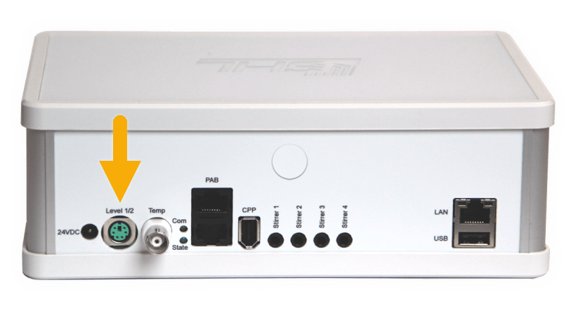
- Connect the float or optical sensor to the Green port labeled, Level 1 / 2 on the Standalone Doser
If you are planning to use 2 sensors for your ATO control:
- Connect the tail-end of the Level Sensor splitter cable to the Doser
- Connect each sensor to the Y-end of the splitter cable

Create the ATO function
1. Connect to your SA Doser via GCC or GHL Connect app
2. Press the Menu icon, select Control, then select Level
3. Choose an unused CONTROL CIRCUIT
4. Select your desired ATO function from the list of operation modes
About Operation mode
The Operation mode you select will depend on how you wish to use the ATO function
Auto Top Off: Normal 1-sensor ATO (most popular option)
Min/Max control: 2-sensor ATO; one sensor is lower and one sensor is upper. When the lower sensor is triggered, ATO pump will run, then stop when the water level reaches the upper sensor
ATO w/ 2 sensors: Both sensors placed side-by-side; ATO is triggered only when both sensors detect low water level


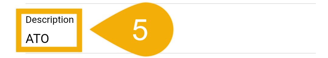
5. Type-in a description for this function; ATO
6. Set the Maximum on-time
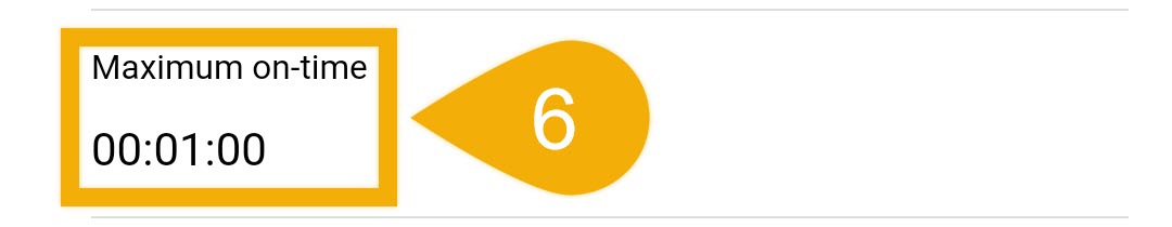
The max on-time is the failsafe feature that turns OFF the assigned pump head in case the assigned level sensor does not respond. The time you set is the maximum time the function is allowed to run for before this failsafe is triggered. If this time limit is met, the doser will automatically turn OFF the pump and trigger an alarm (RED flashing light).
For example, if you set this feature to 5 minutes, you allow the assigned ATO pump to run for up to 5 minutes. If the 5 minute time limit expires, the failsafe will be triggered and an alarm will be activated. When this happens, the doser’s LED indicator will begin flashing RED.
To disable this feature, set the Max on-time to (0).
We recommend setting a time that will give the assigned ATO pump enough time to dispense the needed amount of ATO water.
7. Select if you want the alarm to be automatically reset after being triggered. If enabled, the alarm will reset itself after normal conditions are detected.
If this feature is left disabled, the alarm will remain active until it is manually reset.

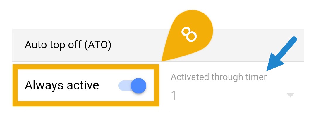
8. If you would like to use the ATO function 24/7, leave this as-is.
If you prefer to only run the ATO on certain days and/or times, disable this option and specify the TIMER number that will be responsible for determining when the ATO can run.
9. Save settings, then press the back arrow (top left of screen)
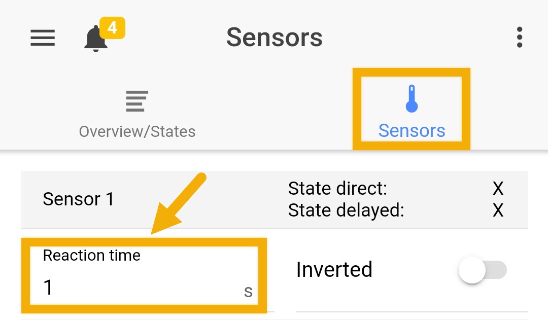
Want to delay the reaction time of a sensor?
Delaying the reaction time of a sensor can prevent the pump head from switching ON / OFF too often. If you would like to delay the reaction of a sensor, press the back-arrow, select the Sensors tab, specify the Reaction time of the selected sensor, then press SAVE.
Assign ATO function to pump head
1. Press the Menu icon, press the back arrow, and select Dosing pumps
2. Select the dosing pump that you wish to use as your ATO pump
3. Type-in a description; ATO
4. Select Container is EMPTIED
")
")
")
If you’d like to keep track of how much ATO water your aquarium uses on a daily basis, enable Record dosages. This will allow the doser to record how often the ATO pump turns ON and how much is dispenses each time. This data can later be viewed on a chart.
![]()
NOTE: In order for the SA Doser to properly record the amount of mL dispensed, the pump head being used MUST BE CALIBRATED. You will have the option to do this later-on.
5. In the Container section, type-in the Capacity of your ATO container in mL, then press REFILL CONTAINER and type-in how many mL are now in your ATO container, then press SAVE
If you would like the SA Doser to notify you when the container is at or below the minimum threshold, enable the option “Alarm if below minimum” and specify the minimum point.
")
6. In the Pump settings section, set the pump speed to (3) and press SAVE.
7. In the Pump reacts to section, select Level control, then select the Control Circuit number you chose earlier.
For example, if you setup your ATO function on Control Circuit 1, choose “Level control index 1”.
8. Set the “Level control function” to Fill water and press SAVE
")
How-to videos
ATO setup via GHL Connect app
ATO setup via GHL Control Center