About AWC Control via the ProfiLux
AWC control via the ProfiLux involves the use of 2 level sensors. These sensors can be either GHL float or optical sensors. They tell the ProfiLux when to stop draining and filling during the water change. The pumps that will be responsible for handling your AWC task can be either two dedicated utility pumps (connected to powerbar socket) or two dedicated GHL Dosing pump heads.
When a water change event begins, the assigned AWC DRAIN pump will turn ON and remove water from your system. This pump will continue running until the water level reaches the lower sensor. When this happens, the AWC DRAIN pump will turn OFF and the AWC FILL pump will turn ON. This fill pump will then stay ON until it reaches the upper sensor. When the normal water level is reached, the fill pump will turn OFF and the AWC task will be complete.
Before you begin
- If you are not familiar yet with the operating concept of the ProfiLux Controller, we highly recommend to first read the Knowledgebase Article “How the ProfiLux Controller works“. It gives you an understanding of the basics and the operational concept of the controller.
- Make sure you have all the correct parts on-hand. (see also list below)
| You will need… |
| Any combination of 2 GHL Level sensors; float (PL-1889) or optical (PL-1890) |
| Matching bracket for float (PL-0080) or optical sensor (PL-0723) |
| PL-LF-Base2 assembly rod (PL-1095) |
| 2x Dedicated pumps for AWC; utility or dosing pump heads |
| Optional: Level sensor splitter cable (PL-0081) |
The PL-LY-Splitter Cable (PL-0081) enables you to connect two sensors to one level port.
In order for you to setup AWC control on a ProfiLux Mini or Light controller, you will need the ProfiLux Mini / Light Adapter (PL-2024). This accessory is sold separately and can be found at the GHL store or GHL USA store.
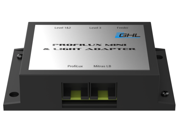
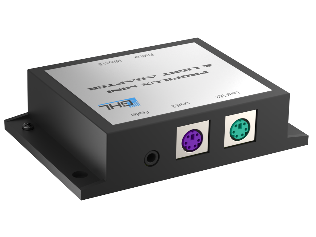
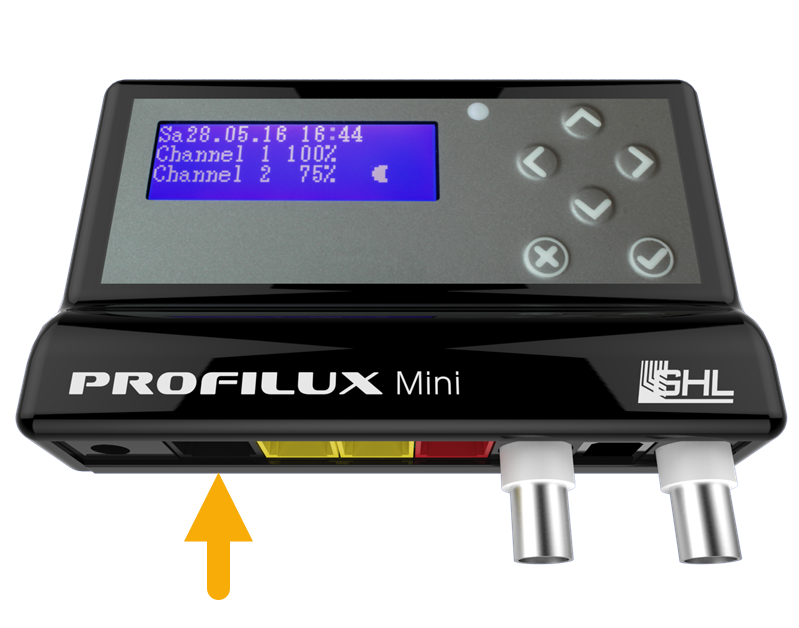
With this accessory in-hand, you can take the included cable and connect it to the adapter (port labeled ProfiLux). Take the other end of the cable and connect it to the Black port as indicated below. Afterwards, you can connect your level sensor to the adapter, then follow the steps shown in Create the AWC function.
Connect your GHL Sensors to an available level port
You can find level ports on your ProfiLux Controller (starting with model 3), the Expansion Box, or an Expansion Card.
Connecting to ProfiLux:
Take note which color port on the ProfiLux you are connecting the sensor(s) to
- Purple port: Level 1 / 2
- Green port: Level 3 / 4
If a single sensor is connected directly to a Level-port, the Level sensor will be assigned to the first number of that Level-port.
For example, if a single sensor is connected to Level 1/2, the sensor would automatically be assigned as Level sensor #1.

Level ports on the ProfiLux Controller
Connecting to an Expansion Card or a Expansion Box
If you are connecting the sensor(s) to an Expansion Card or Expansion Box, the Level-port numbering will continue beyond Level 3 / 4.
- For example, if you have a PLM-4Level Expansion Card, the Level-port numbering would be 5 / 6 for one port and 7 / 8 for the second port.
- If you do not have any Level-port expansion cards on the P4 / 4e and instead have an Expansion Box 2, Level 1 / 2 on the EXB2 would actually be Level 5 / 6.

Expansion Card PLM-4LEVEL with 4 Level-ports

Expansionbox 2 for ProfiLux
- and starts with the sensors permanently installed in the ProfiLux,
- then the sensor inputs of expansion cards (if available) follow,
- next, the fixed inputs of the first Expansion Box are counted,
- then the sensor inputs of expansion cards in the first expansion box.
- The numbering of sensor inputs of further Expansion Boxes is continued with the same system.
Create the AWC function
- Press the Menu icon, select Control, select Level
- Select an unused CONTROL CIRCUIT


About Operation mode
The Operation mode you select will depend on how you wish to use the AWC function
Water change: Standard WC option
ATO & Water change: Similar to Water Change, but also includes the ATO function where the upper (max-point) sensor will serve for both ATO and AWC functions
If ATO & WC is selected, select if you want the ATO function always active.
3. Set the Operation mode to either Water change OR ATO & Water change
4. Type-in a description; AWC
5. Set the Maximum on-time
6. Select if you want the alarm to be reset automatically after the fail-safe has been triggered. With this option selected, the alarm will automatically be reset once the water change sensors detect normal conditions. If left disabled, the alarm will remain until manually reset.
7. Select the TIMER number that will be responsible for activating the AWC function
Select a TIMER number that is currently not being used. You will go to this TIMER function and configure it later.
8. Select the sensors that will be used for this function, then press SAVE

For example, if you have a single sensor connected to the Level 1 / 2 port, select (1)
If you are using a splitter cable and have both sensors connected to Level port 1 / 2, select (1) and (2)
Same rules apply if these sensors are connected to Level port 3 / 4, 5 / 6, etc.
About Maximum on-time
This is the fail-safe that will turn OFF the assigned Powerbar outlets or dosing pumps in case the assigned float and/or optical sensors do not respond. If the specified time limit expires, the fail-safe will be triggered with an alarm and the assigned outlets and dosing pumps will turn OFF.
To disable this feature, set the Max on-time to (0)
Did you select ATO & Water change?
If you selected the ATO & Water change operation mode, select if you want the ATO function to run 24/7 or be controlled by a TIMER function, Always ON (as shown). If you want the ATO to be controlled by a timer, disable this option and select the timer number that will control it. You will need to go to that timer function and specify the ON/OFF time and day after you complete the AWC setup.
")
Want to delay the reaction time of a sensor?
Delaying the reaction time of a sensor can prevent the sensor/outlet from switching ON/OFF too often. If you need to delay the reaction of a level sensor, press the back-arrow, select the Sensors tab, specify the Reaction time of the selected sensor, then press SAVE.

Create the AWC schedule
- Press the back-arrow, press the Menu icon, press the back-arrow, select Processes
- Select an unused Timer function
")
")
3. Press the Switch mode tab, select Event start, then type-in a description
4. Press the Schedule tab, press ADD and specify the time the AWC will begin.
If you want to do multiple WC throughout the day, press ADD again and specify each starting time.
5. Select a Day mode, then press SAVE
About Day mode
Day mode allows you to specify the way the ProfiLux should run the timer schedule.
Special weekdays: Allows you to choose the days of the week to activate the WC
Day intervals: Allows you to choose how often to run the WC in intervals
For example, Repeat every 3 days = WC will run every 3 days
Starting in is a delay. If you want to delay the WC, specify by how many days
")
")
Assign the AWC function
1. Press the back-arrow, press the Menu icon, select Switch channels
2. Select the switch channel (Powerbar outlet) that has the AWC DRAIN pump connected to it
3. Type-in a description; AWC DRAIN
4. Set the function to Drain water and select the Control Circuit number you used when you created the AWC function, then press SAVE
For example, if you created the AWC function on Control circuit 1, set the function to DRAIN WATER 1.
If Control circuit 2 was used, set the function to DRAIN WATER 2.
")
")
")
5. Press the back-arrow, then select the outlet that has the AWC FILL pump connected to it
6. Type-in a description; AWC FILL
7. Set the function to Fill water AWC only, select the Control circuit number you used when you created the AWC function, then press SAVE
Similar to step 4, if you created the AWC function on Control circuit 1, set the function to FILL WATER (AWC ONLY) 1.
")
Did you select ATO & Water Change?
If during the AWC function setup, you selected the Operation mode, ATO & WATER CHANGE, you can assign the function Fill water (ATO only) to a switch channel with a separate pump for filling.
If you want to use the same pump for filling ATO and AWC, assign the Fill water function to the switch channel with this pump.
")
Want to use a GHL-Doser for AWC?
To use a GHL-Doser for AWC, you can assign switch channels to the corresponding dosing pumps:
- Press the back-arrow, press the Menu icon, select Dosing pumps
- Select the pump you want to use as DRAIN pump
- Type-in a description; AWC drain
- Set Pump reacts to Switch channel and select the number of the switch channel to which you have assigned the function Fill water AWC only
For example, if you have assigned the Control Circuit with the ATO function to switch channel 1, set it to SWITCH CHANNEL 1.
Repeat step 2-4 fo the FILL pump.
HOW TO VIDEOS
AWC idea: Stop AWC if reservoir is empty
ProfiLux (3 and higher) controller owners have the option to setup a special condition which would prevent the AWC task from starting if there is not enough water in the WC reservoir.
If you wish to setup this level of control, follow these steps.
| Item | Purpose |
| 1x GHL Float sensor (PL-1889) | Will be placed in the water change reservoir; this will stop the AWC from starting if triggered |
| 1x Float sensor bracket (PL-0080) | Holds float sensor to assembly rod |
| 1x PL-LF-Base2 assembly rod (PL-1095) | Holds float sensor and bracket to your reservoir |
| Optional: Level sensor splitter cable (PL-0081) | Necessary if you do not have an available LEVEL port on your ProfiLux; allows you to connect 2 sensors to a single LEVEL port |
By using the GHL float sensor and placing it in your water change reservoir, you can setup a Programmable Logic function that will prevent the AWC task from starting ONLY IF the float sensor in the reservoir is out of the water. When this happens, the sensor will trigger the alarm and the ProfiLux will notify you.
Connect GHL float sensor
1. Take the GHL float sensor and connect it to an available LEVEL port on your ProfiLux.
If you do not have an available level port and instead have a single sensor already connected to a port, you can use the PL-LY splitter cable so you can connect 2 sensors to the single LEVEL port.
2. Position the float sensor near the bottom of your reservoir.
Create function for reservoir sensor
1. Connect to your ProfiLux, press the Menu icon, select Control, select Level
2. Select an unused Control Circuit
3. Set the Operation mode to Auto Top Off
4. Type-in a description: AWC res.sen
5. Set the Maximum on-time
1 minute or less is OK.
6. Enable Reset error automatically
7. Select the sensor number where you have the reservoir sensor connected
8. Press SAVE
Create Programmable Logic function
Now that the float sensor function is setup, it’s time to create a PL function which will tell the ProfiLux when it can run the AWC task.
1. Press the back-arrow, press the Menu icon, press the back-arrow and select Programmable Logic
2. Select an unused PL gate
3. Set the Function to AND
4. Set Input 1 to Fill water AWC only, then specify the Control Circuit number you used when you created the AWC function
For example, if you created the AWC function on Control Circuit #1, set Input 1 to Fill water AWC only 1
5. Set Input 2 to Fill water ATO only, then specify the Control Circuit number you used when you created the function for the reservoir float sensor.
For example, if you created the function for the reservoir sensor on Control Circuit #2, set Input 2 to Fill water ATO only 2
6. Invert the function for Input 2
7. Press SAVE


8. Select another unused PL gate and set the function to AND
9. Set Input 1 to Drain water, then specify the Control Circuit number you used when you created the AWC function
For example, if the function was made on CC #1, set Input 1 to Drain water 1
10. Set Input 2 to Fill water ATO only, then specify the Control Circuit number you used when you created the function for the reservoir float sensor.
For example, if you created the function for the reservoir sensor on Control Circuit #2, set Input 2 to Fill water ATO only 2
11. Invert the function for Input 2
12. Press SAVE

Assign PL functions to switch channels
With the PL functions created, you can now assign them to the respective switch channels which are used for the AWC task.
1. Press the Menu icon and select Switch channels
2. Select the switch channel number that was assigned to the AWC Filling pump
3. Set the function to Programmable Logic and select the Gate number you used when you created the PL function for the AWC Filling task.
4. Press SAVE, then press the back-arrow
5. Select the switch channel number that was assigned to the AWC Drain pump
6. Set the function to Programmable Logic and select the Gate number you used when you created the PL function for the AWC Drain task.
7. Press SAVE