")
About this article
This article will show you how to connect a Gen1 GHL Dosing Unit (Slave) to your ProfiLux controller (3 and higher). Since this device is NOT a PAB device, the setup steps will be different for this doser product.
These steps only apply to Gen 1 SLAVE Dosers.
Due to the hardware limits of the standalone Gen 1 Doser, this model is NOT capable of being controlled by the ProfiLux
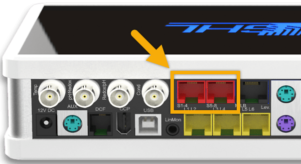
In order for the ProfiLux to control this kind of doser, you will need to have an available S-port on your controller head unit. On ProfiLux 4 controllers, these ports are colored RED and labeled S1-S4 and S5-S8.
If you have a ProfiLux 4e controller, you will need to add the S-port by installing the PLM-2L4S expansion card (PL-0000).
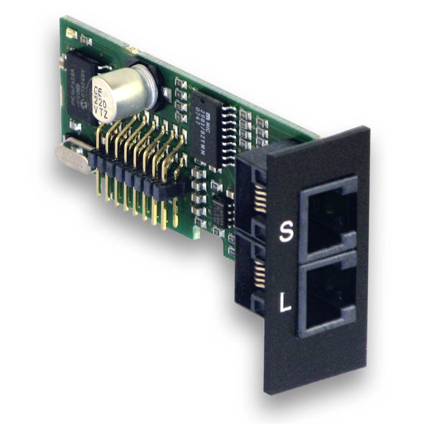
Connect Doser communication cable to ProfiLux
- Take the communication cable that came with the Gen1 slave doser and connect one-end to the back of the doser and other-end to the RED port on the ProfiLux head unit
If you have a ProfiLux 4e head unit, connect the communication cable to the S-port on the PLM-2L4S expansion card.
App: Enable digital communications
- Connect to your ProfiLux, press the Menu icon and select Switch channels
- Select Configure Digital Powerbars/Dosing Units
- Choose the S-port where you have connected your doser and press SAVE
If you connected the doser to the S1-S4 port, choose “Digital device connected on S1-S4”
If you connected the doser to the S5-S8 port, choose “Digital device connected on S5-S8”


App: Program doser (Set pump numbering)
- Select Program numbering or initial state
- Select Numbering of a dosing pump stations (Dosing unit)
- Set the numbering of this dosing pump station, then press NEXT
In this step, you will assign these pump heads to specific switch channels. You should assign these pump heads to non-physical switch channels.
For example, if you have a Powerbar-6E already on Switch channels 1-6 and this dosing unit is connected to the S1-S4 port…assign the pumps to start at 7 (7, 8, 9, 10)
If you have the doser connected to the S5-S8 port, note that the pump heads can be assigned to switch channels starting at 25.


4. Press Program Now

App: Assign Dosing Pump channels to switch channels
Now that you have programmed the dosing unit and assigned each pump each to a switch channel, the next step will be to assign the Dosing Pump channels to these switch channels.
The Dosing pump channels are where you will create your dosing schedule later.
- Select the switch channel where you assigned each pump head and set their functions to a dosing pump channel.
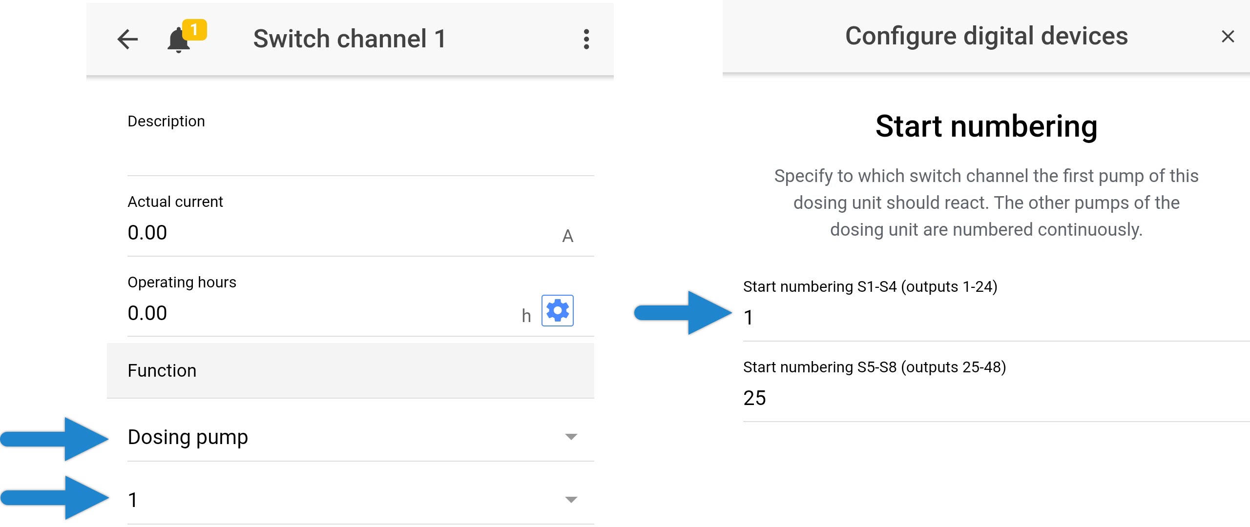
Using the illustration above, notice how we’ve assigned our dosing unit to switch channels 1 – 4 (right). Looking at the left photo, you can see we then chose the corresponding channel and assigned a Dosing pump channel.

App: Create your dosing schedule
Now that your dosing pump is programmed, you can setup your dosing schedules for each pump head.
GCC: Enable digital communications
1. Connect to your ProfiLux and go to the Switch channels and outlets page
2. Choose the S-port where you have connected your doser
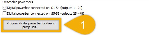
If you connected the doser to the S1-S4 port, choose “Digital powerbar connected on S1-S4”
If you connected the doser to the S5-S8 port, choose “Digital powerbar connected on S5-S8”
3. Save settings
")
GCC: Program doser (Set pump numbering)
1. Click Program digital powerbar or dosing pump unit
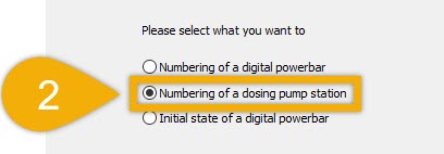
2. Select Numbering of a dosing pump station
3. Set the numbering of this dosing pump station
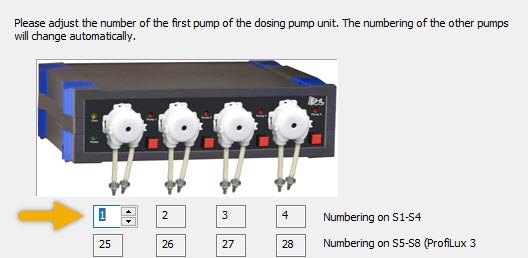
In this step, you will assign these pump heads to specific switch channels. You should assign these pump heads to non-physical switch channels.
For example, if you have a Powerbar-6E already on Switch channels 1-6 and this dosing unit is connected to the S1-S4 port…assign the pumps to start at 7 (7, 8, 9, 10)
If you have the doser connected to the S5-S8 port, note that the pump heads can be assigned to switch channels starting at 25.
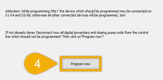
4. Click Program Now
GCC: Assign Dosing Pump channels to switch channels
Now that you have programmed the dosing unit and assigned each pump each to a switch channel, the next step will be to assign the Dosing Pump channels to these switch channels.
The Dosing pump channels are where you will create your dosing schedule later.
1. Select each switch channel and assign it to a Dosing pump channel
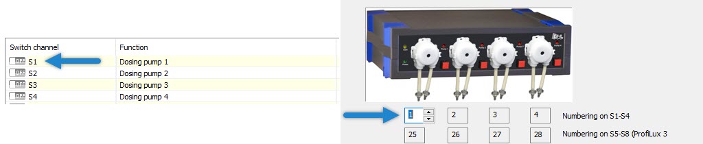
Using the illustration above, notice how we’ve assigned our dosing unit to switch channels 1 – 4 (right). Looking at the left photo, you can see we then chose the corresponding channel and assigned a Dosing pump channel.
GCC: Create your dosing schedule
Now that your dosing pump is programmed, you can setup your dosing schedules for each pump head.