
About GHL Flow Sensors
GHL Flow Sensors are high performance sensors that can be used for a wide range of applications such as monitoring the flow rate going through your media reactor, UV sterilizer or return pump. With these sensors, you can configure the ProfiLux to continuously monitor flow and notify you if the flow drops below a certain LPH or GPH value. You also have the option to integrate flow monitoring and 1-10V pump control to maintain a specific flow rate.
This article will show you how to complete the installation and basic setup process for monitoring flow rates through your ProfiLux (3 and higher) controller.
Getting started…what you will need
In order to proceed, you will need the following:
| Item | Purpose |
| GHL Flow Sensor | For measuring flow rate |
| Matching fittings | For connecting flow sensor in new or existing plumbing |
| Available Level port on ProfiLux | For connecting flow sensor to ProfiLux |
In order to install the FS to your plumbing, you will need to have the correctly sized fittings for your sensor. Use the table below to make sure you have the correct fittings. If you need to purchase these fittings, they can be found at your preferred GHL dealer or directly from the GHL International or GHL USA online shop.
Metric sizing
| Flow sensor size | Fitting (socket) size | Part number |
| 2000 l/h | 16mm pipe | PL-1664 |
| 5000 l/h | 20mm pipe | PL-1665 |
| 9000 l/h | 25mm pipe | PL-1666 |
Imperial sizing (USA)
| Flow sensor size | Fitting (socket) size | Part number |
| 2000 l/h | Unavailable | Unavailable |
| 5000 l/h | 1/2" PVC pipe | PL-1667 |
| 9000 l/h | 3/4" PVC pipe | PL-1668 |


Install flow sensor in your plumbing
- Make sure the inner diameter of your plumbing is NOT smaller than the ID of the flow sensor
- Take note of the flow direction arrow and install accordingly
- Avoid installing flow sensor directly in front of any 45° or 90° bends
- Make to have a straight run in front of and after the flow sensor; the longer the straight-run, the more accurate the measurement
Solids, sediment, and dirt can impact the measurement accuracy of the flow sensor and possibly destroy it. For this reason, we recommend installing your sensor AFTER a filter.
With flow sensors, you have the option to plumb it directly in-line with your plumbing or in a bypass. There are however certain instances when the sensor must be installed in a bypass. More info on that below.
When to install in a bypass…
Installing the flow sensor in a bypass becomes necessary if the total flow rate going through your plumbing exceeds the maximum measurable flow rate of your flow sensor.
If the sensor is installed in a bypass…
You must calibrate the sensor so it can provide accurate measurements.
- Find a suitable location for your flow sensor and glue the flow sensor fittings to your plumbing
- Connect the flow sensor to the matching fittings
Connect flow sensor to ProfiLux
Now that your flow sensor is plumbed, you can move on to connecting it to your ProfiLux.
The ProfiLux controller can individually monitor up to 4 flow sensors. These sensors can be connected to any available level port on the ProfiLux head unit or Expansion card.
Flow sensors can only be connected to the ProfiLux head unit or expansion cards that have LEVEL inputs built-in. If you have an Expansion Box and want to connect a flow sensor to this EXB, make sure you have an expansion card installed inside; the Flow sensor MUST be connected to this expansion card.
1. Take the cable that was included with the flow sensor and connect the M12-screw connector to the top part of the flow sensor
2. Once the cable is fully seated onto the flow sensor, turn the locking nut clockwise to secure the cable connection

3. Take the other-end of the cable and connect it to an available LEVEL port on your ProfiLux or Expansion card
If connecting sensor to ProfiLux head unit, take note which color port you are connecting the sensor(s) to
- Purple port: Level 1 / 2
- Green port: Level 3 / 4
The flow sensor will be assigned to the first number of that Level-port. For example, if you connect a flow sensor directly to the Level 1/2, that sensor would automatically be assigned as Flow sensor #1.


Configure flow sensor settings
With the sensor plumbed and connected to your ProfiLux, you can now connect to your ProfiLux and configure the flow sensor settings and behavior.
If you are configuring your flow sensor settings using GHL Control Center, you can still use these steps as a guideline for the setup process. Even though the visuals will appear differently, the steps are nearly identical.
1. Connect to your ProfiLux using the GHL Connect app or GHL Control Center
2. Press the Menu icon, select Control, then select Flow sensors
In GHL Control Center, press the (+) icon beside Probe/Sensor controls (far left side of screen) and select Flow-sensor.
3. Type-in a description for your flow sensor
4. Select your unit of measurement; l/h or g/h
5. Type-in your desired flow rate
6. Select the Level port number for where you have your flow sensor connected, then press SAVE
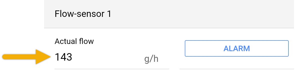
If you chose the correct Level port number, you will see a value displayed in the Actual flow section.


Flow sensor installed in a bypass?
If your flow sensor is installed in a by-pass, follow these steps. If not, you can skip this part.
For example, if you have a 5000 l / h sensor used in a bypass and only half of the water flows through the bypass, you must calibrate the sensor so it takes the adjusted flow rate into account. Both the GHL Connect app and GHL Control Center software offers a tool to help you determine the correct calibration value.
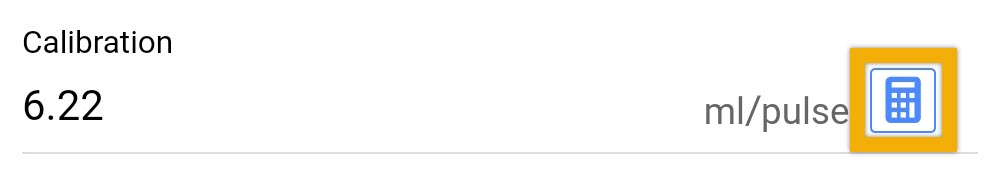
1. In the Calibration section, press the calculator icon to enter the calibration settings for the chosen flow sensor
2. Select your flow sensor model
3. Select Flow sensor is operated in a bypass (as shown)
4. Type-in the approximate percentage of your flow that is going through the bypass
The “determined calibration value” field will automatically be filled-in for you based on the percentage you enter.
5. Press APPLY and SAVE to store your calibration

Setup alarm conditions
Now that the flow sensor is activated and monitoring your flow rate, the next step will be to setup the alarm conditions so you can receive notifications.
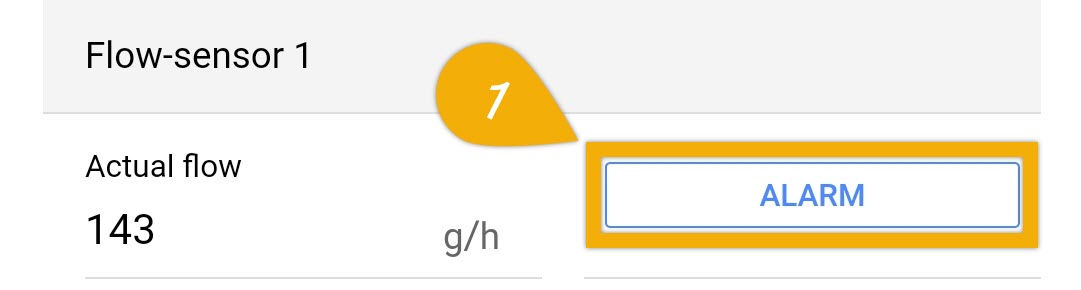
1. Press the ALARM button to view the alarm settings for the chosen flow sensor.
2. In the Alarm threshold field, type-in the flow rate for when the alarm should be triggered. If the flow rate reaches this value or lower, the alarm will be activated.
3. If your flow sensor is measuring a pump which turns OFF when a Maintenance mode, choose the maintenance mode that will temporarily deactivate this flow sensor
4. If your flow sensor is measuring a pump which turns OFF when a Feed pause is activated, choose the feed pause that will temporarily deactivate this flow sensor
5. Press APPLY, then press SAVE to store these settings.
")
OPTIONAL: Control 1-10V pump via Flow Sensor
If you have a 1-10V controllable pump and want to use the flow sensor to maintain a specific flow rate, follow the steps below.
In order for the flow sensor to manage and maintain the flow rate of a 1-10V pump, the control cable from the pump must be connected a 1-10V port either on the ProfiLux head unit, expansion card or Expansion Box 2.
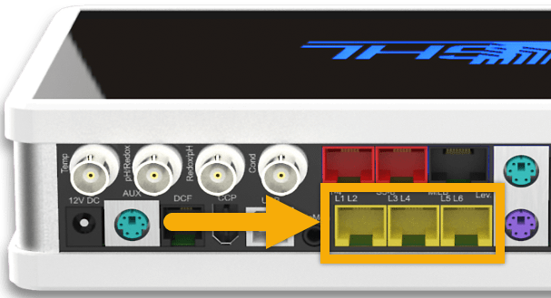
If the pump manufacturer provides a GHL-compatible control cable, connect it to one of the yellow 1-10V ports on the ProfiLux.
If the pump manufacturer does not provide a compatible control cable, you can still connect it to the ProfiLux. To do this, you will need a GHL Breakout Box (PL-1680) and whichever control cable the manufacturer provides. One-end of this control cable is then cut and connected to the GHL Breakout Box. The BO box is then connected to the ProfiLux 1-10V port.
IMPORTANT
Take note of which port you are connecting the pump control cable to. You will need to know this for the steps below.
1. Press the Menu icon and select 1-10V interfaces
2. Select the 1-10V interface number where you have your pump connected
For example, if your pump is connected directly to the L5 / L6 port, select 1-10V interface #5 (as shown).
3. Set the function to Constant flow and choose the flow sensor number which will be controlling the speed of your 1-10V pump


4. Press SAVE
The flow sensor will now maintain the flow rate based on the “Nominal value” you set in the flow sensor settings page.