
About Programmable Logic
Programmable Logic is a special feature that allows you to customize the behavior of a particular function. PL becomes especially useful in cases where a certain Powerbar socket should react to more than one function.
Within the PL settings page, you will be up to 32 “gates”.
Here is where you can choose an available gate and specify how one or more function should react under specific circumstances.
The most commonly used PL functions are: Delay ON, Delay OFF, AND, and OR
This article will provide you with examples on how to use Programmable Logic. Simply choose the topic that applies to you and follow the steps provided.
Assigning 2 functions to a Powerbar socket
This section will provide you with the how to steps for creating the necessary PL function so you can assign 2 functions to the desired Powerbar socket.
— Combine 2 Feed Pauses (AND)
Scenario: You created 2 Feed Pauses where each are set to run for different amounts of time; Ex. 5 min / 15 min. You would like to have a single Powerbar socket react to both these FP functions.
Before you proceed with the steps below, you should already have both Feed Pause functions created. If you have not done so yet, click here for the how-to steps.
NOTE: You will ONLY need to create the function. You do not have to assign this function to an outlet just yet.
- Press the Menu icon and select Programmable Logic
- Select an unused Gate
- Set the function to AND
- Set Input 1 to Filter, then specify which feed pause number to use
- Set Input 2 to Filter, then specify the other feed pause number to use
For example, if you have your FP functions on Feed Pause 1 and Feed Pause 2, set Input 1 to Filter 1 and Input 2 to Filter 2. - Press SAVE
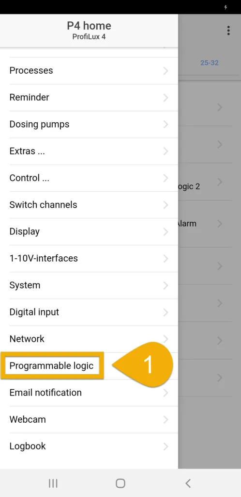
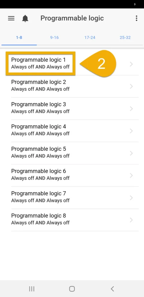
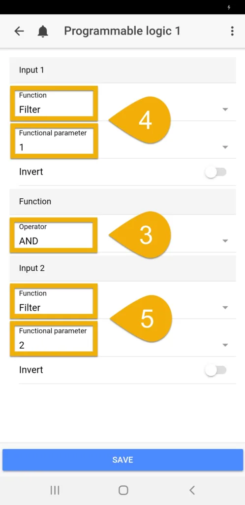
You have now created a PL function which contains the combination of two different Feed Pause functions. The next step will be to assign the PL function to the Powerbar socket(s) which you want reacting to this function.
Assign Programmable Logic function to Powerbar socket
- Press the back-arrow, press the Menu icon, select Switch channels
- Select the Powerbar socket that you want reacting to this PL function
- Type-in a description
- Set the function to Programmable Logic and select the Gate number you used when you created the PL function.For example, if you created the PL function on Gate #1, select Programmable Logic 1
- Press SAVE
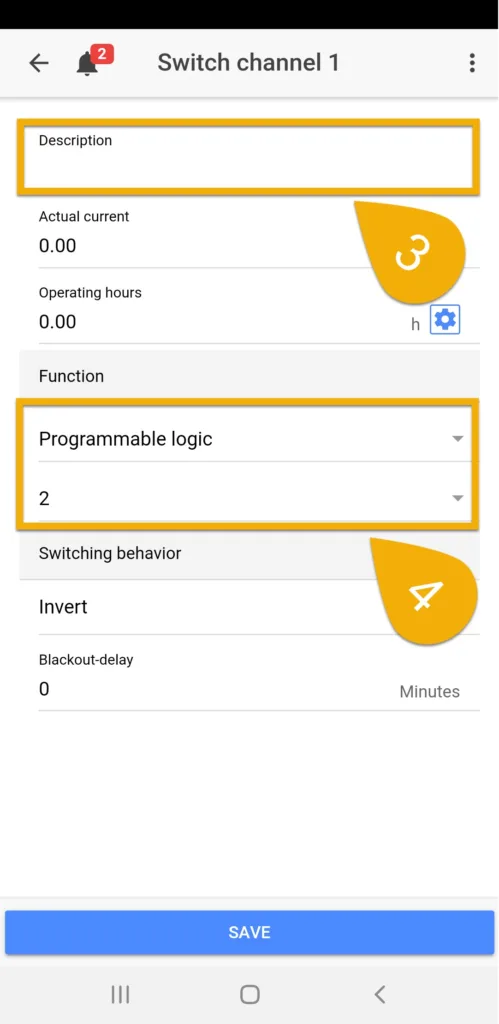
You have now assigned this PL function to a Powerbar socket. Since this PL function contains the combination of 2 FP functions, the ProfiLux will control the Powerbar socket according to both Feed Pause functions.
When either FP is activated, the assigned socket will react accordingly.
— Combine a Feed Pause and Timer (AND)
Scenario: You created a Feed Pause function and a Timer function for your skimmer which is connected to Powerbar socket #1. You would like to have this socket (1) run according to the TIMER schedule, but turn OFF if the FP is activated during the ON time of your timer.
Before you proceed with the steps below, you should already have the Feed Pause and Timer functions created. If you have not done this yet, click the links below for the how-to steps.
Create Feed Pause function
Create Timer function
NOTE: You will ONLY need to create the function. You do not have to assign any functions to an outlet just yet.
- Press the Menu icon and select Programmable Logic
- Select an unused Gate
- Set the function to AND
- Set Input 1 to Filter, then specify which feed pause number to use
- Set Input 2 to Timer, then specify the timer number to useFor example, if you have your FP function on Feed Pause 1 and Timer function on 1, set Input 1 to Filter 1 and Input 2 to Timer 1.
- Press SAVE


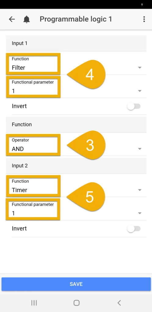
You have now created a PL function which contains the combination of two different functions. The next step will be to assign the PL function to the Powerbar socket(s) which you want reacting to this function.
Assign Programmable Logic function to Powerbar socket
- Press the back-arrow, press the Menu icon, select Switch channels
- Select the Powerbar socket that you want reacting to this PL function
- Type-in a description
- Set the function to Programmable Logic and select the Gate number you used when you created the PL function. For example, if you created the PL function on Gate #1, select Programmable Logic 1
- Press SAVE

You have now assigned this PL function to a Powerbar socket. Since this PL function contains the combination of a FP and Timer function, the ProfiLux will control the Powerbar socket according to both functions.
If a FP is activated during the timer’s ON-time, the assigned socket will react accordingly.
— Stop GHL Doser ATO pump during Maintenance mode
Scenario: You are currently using a GHL dosing pump head as your ATO pump and want to turn this pump OFF if it happens to be ON when you want to activate a maintenance mode.
Before you proceed with the steps below, make sure you already setup your ATO function and assigned a dosing pump head to be used for the ATO task. If you have not done this yet, click the link below for the how-to steps.
NOTE: You will ONLY need to create the function. You do not have to assign any functions to an outlet just yet.
- Press the Menu icon and select Programmable Logic
- Select an unused Gate
- Set the function to AND
- In the Input 1 section, select your ATO function
For example, if your ATO function is currently on Control Circuit #4…you would set Input 1 to Fill Water (ATO only) 4
5. In the Input 2 section, select the Maintenance mode which you want the pump head to react to
For example, if you want to turn OFF the pump head when you activate Maintenance #4, set Input 2 to Maintenance 4
6. Set Input 2 to Inverted (as shown below) and press SAVE
You have now created a PL function which combines your ATO task with your maintenance mode. The next step will be to assign the PL function to the Powerbar socket which the Doser ATO pump reacts to.
Assign Programmable Logic function to Powerbar socket
- Press the back-arrow, press the Menu icon, select Switch channels
- Select the Powerbar socket that you want reacting to this PL function
- Type-in a description
- Set the function to Programmable Logic and select the Gate number you used when you created the PL function. For example, if you created the PL function on Gate #8, select Programmable Logic 8
- Press SAVE
You have now assigned this PL function to a Powerbar socket. Since this PL function combines both your ATO task and Maintenance mode, the ProfiLux will turn OFF the ATO pump head IF it happens to be ON when you activate a maintenance mode.
Assigning 3 or more functions to a Powerbar socket
With the help of Programmable Logic functions, you can create a single PL function which takes existing PL functions and combines them into one single function.
This section will provide you with examples where 3 functions or more functions are combined and assigned to a Powerbar socket.
— Feed mode delay / Feed mode delay / Timer (AND)
Scenario: You want to have your skimmer react to TWO separate feed pauses, each which have their OWN SEPARATE delay times (5 min / 10 min). You also want this skimmer to run according to a timer schedule.
Example:
- Feed Pause – 10 min (with a 5 minute delay ON at the end of the FP)
- Feed Pause – 20 min (with a 10 minute delay ON at the end of the FP)
- Timer – ON between 8:00 – 16:00 (8am – 4pm)
Before you proceed with the steps below, you should already have the Feed Pause and Timer functions created. If you have not done this yet, click the links below for the how-to steps.
Create Feed Pause function
Create Timer function
NOTE: You will ONLY need to create the function. You do not have to assign any functions to an outlet just yet.
Before you proceed with the steps below, you should already have created a FP delay for each FP function. If you have not done this yet, click the link below for the how-to steps.
NOTE: You will ONLY need to create the function. You do not have to assign any functions to an outlet just yet.
- Press the Menu icon and select Programmable Logic
- Select an unused Gate
- Set the function to AND
- Set Input 1 to Programmable Logic, then specify the PL gate you used when you created the first Feed Pause delayFor example, if you have your FP delay on PL gate #1, set Input 1 to Programmable Logic 1
- Set Input 2 to Programmable Logic, then specify the PL gate you used when you created the second Feed Pause delayFor example, if you have your FP delay on PL gate #2, set Input 2 to Programmable Logic 2
- Press SAVE

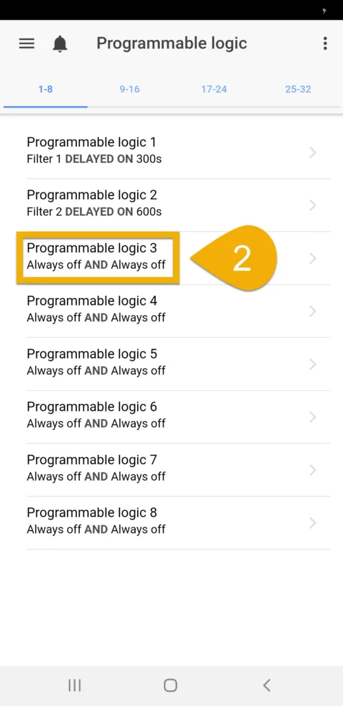
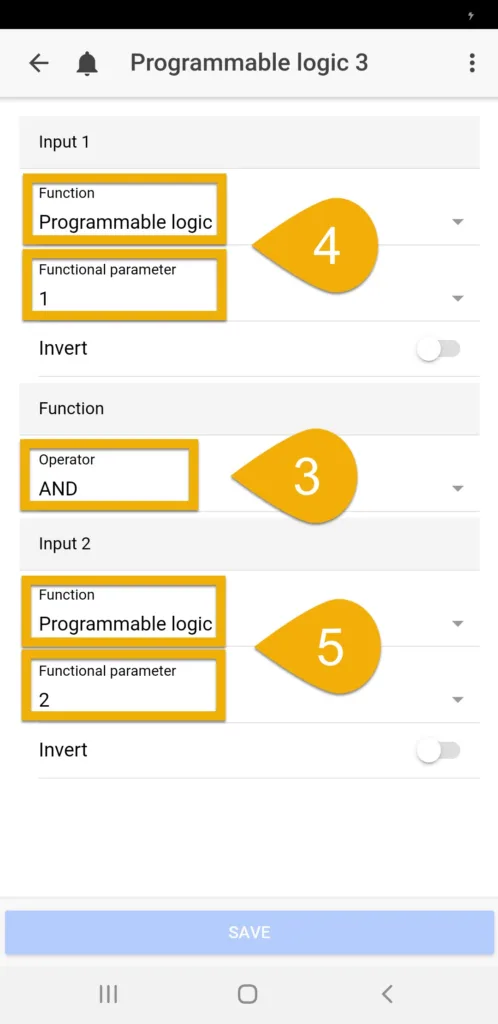
You have now combined both FP delay functions into a single Programmable Logic function. The next step will be to take this PL function and combine it with your 3rd function (TIMER).
To do this, you will create a new PL function which combines the first PL function (FP/FP delays) with your 3rd function.
Create a new PL function to combine existing PL gate with another function
- Press the back-arrow and select an unused Gate
- Set the function to AND
- Set Input 1 to Programmable Logic, then select the PL gate where you combined both FP delaysFor example, if you combined two FP delay functions on Programmable Logic gate #3, select Programmable Logic 3
- Set Input 2 to TIMER and select the TIMER number you used when you created the function
- Press SAVE
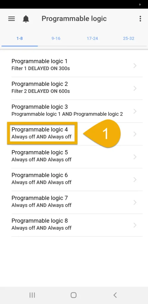
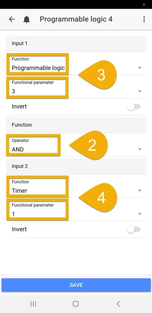
Congratulations!
You have now combined 3 separate functions onto a single Programmable Logic function. Since the 1st PL function contains the combination of 2 functions, you just took this PL function and combined it with a 3rd function on a new PL gate. The combination of all 3 functions (FP delay / FP delay / Timer) is now on this newly created Programmable Logic function.
The next step will be to assign this PL function to the Powerbar socket which you want reacting to this function.
Assign Programmable Logic function to Powerbar socket
- Press the back-arrow, press the Menu icon, select Switch channels
- Select the Powerbar socket that you want reacting to this PL function
- Type-in a description
- Set the function to Programmable Logic and select the Gate number you used when you created the PL function.For example, if your 3 combined functions are located on PL Gate #4, select Programmable Logic 4
- Press SAVE
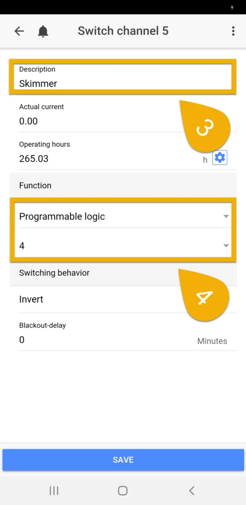
You have now assigned this PL function to a Powerbar socket. Since this PL function contains the combination of 3 functions (FP delay / FP delay / Timer), the ProfiLux will control the Powerbar socket according to these 3 functions.
If any of the two FP modes are activated, the assigned socket will react accordingly.