1-10 V Interfaces
The ProfiLux Controller can control external electronic devices such as coolers, heater, or pumps via 1-10 V interfaces.
- ProfiLux 4/4e has six permanently installed 1-10 V interfaces L1 to L6 (two combined in one connection). With the PLM-2L4S or PLM-4L Expansion cards, the number of 1-10 V interfaces can be increased.
- ProfiLux Mini (WiFi) and ProfiLux Light (WiFi) each have 4 x 1-10 V interfaces installed.
Each interface can be configured separately, and depending on the connected device; the corresponding function* can be assigned. (see also under Functions overview below).
The following example shows how easy it is to control a stream pump via a ProfiLux 1-10V interface.
* Learn more about functions within the operating concept of the ProfiLux controller in the article “How the ProfiLux Aquarium Controller works”.
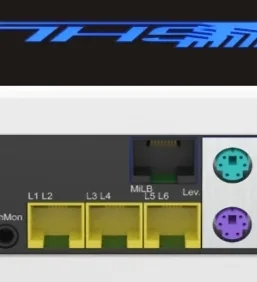
L1-L6: 1-10V interfaces on ProfiLux 4e.
These can then only be switched on or off but not regulated.
Control a controllable stream pump with ProfiLux
Configure the 1-10V interface via GHL Connect App or through the GHL Control Center (GCC).
- Specify which interface is to be used to control the pump
- Assign the pump to this interface
Configure 1-10 V interfaces via GHL Connect App
GHL Connect App
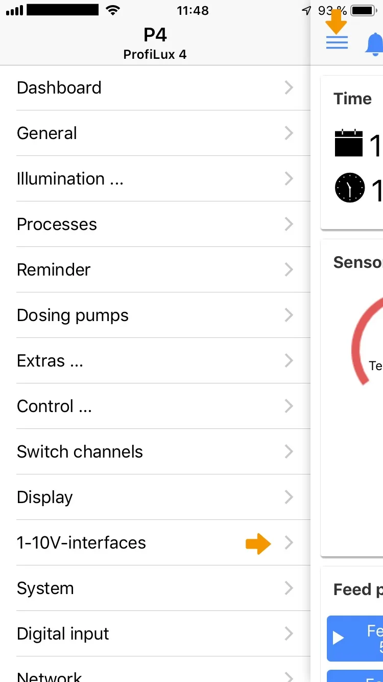
Press the Hamburger menu in the Dashboard of GHL Connect and select 1-10V interfaces.
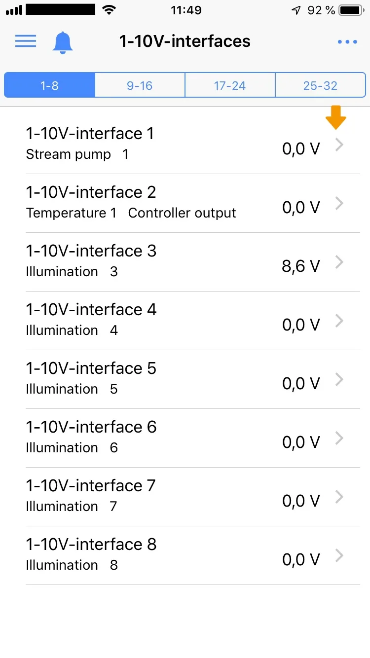
Select the interface to which you want to assign a function.
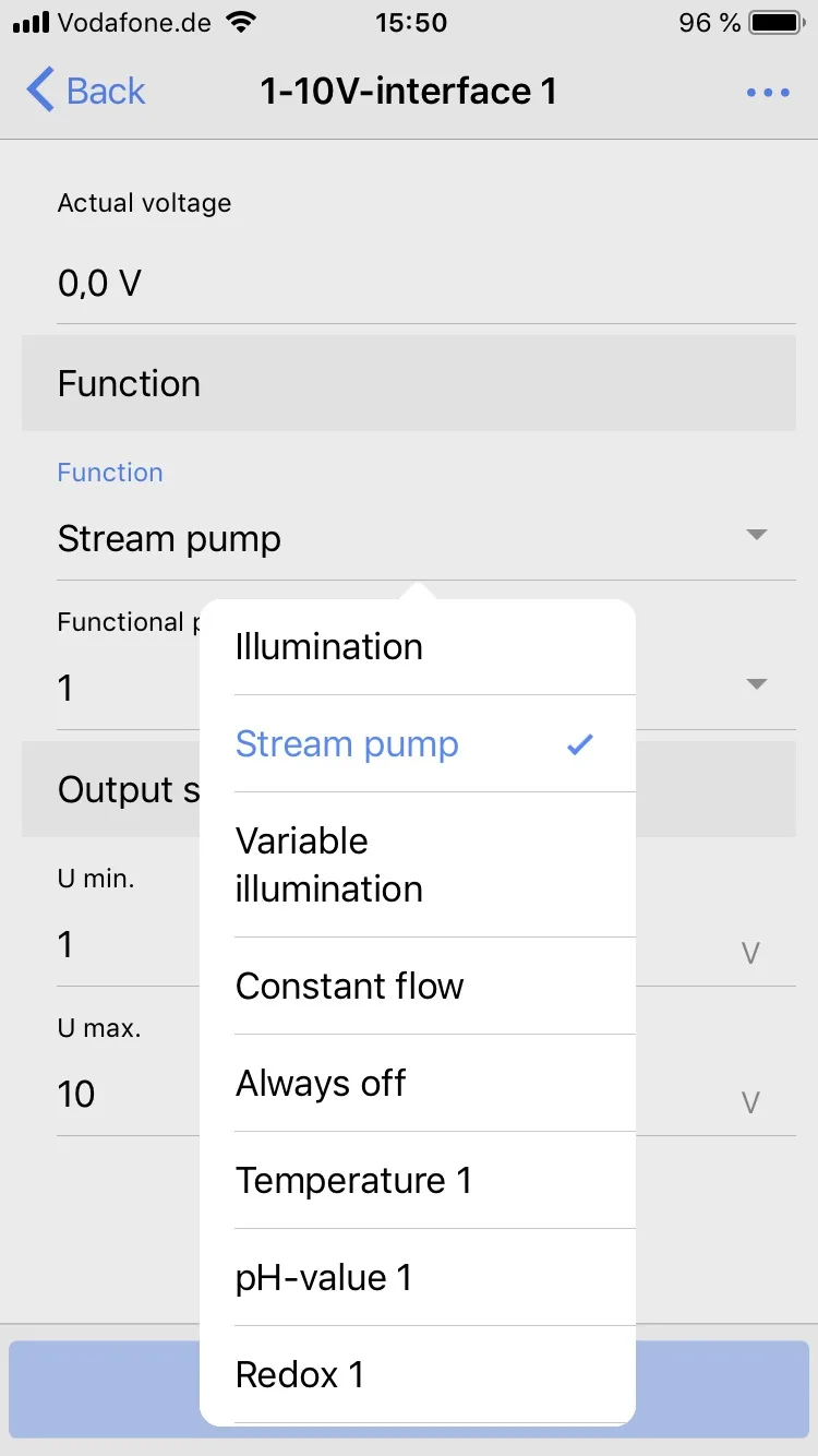
Set Stream pump.
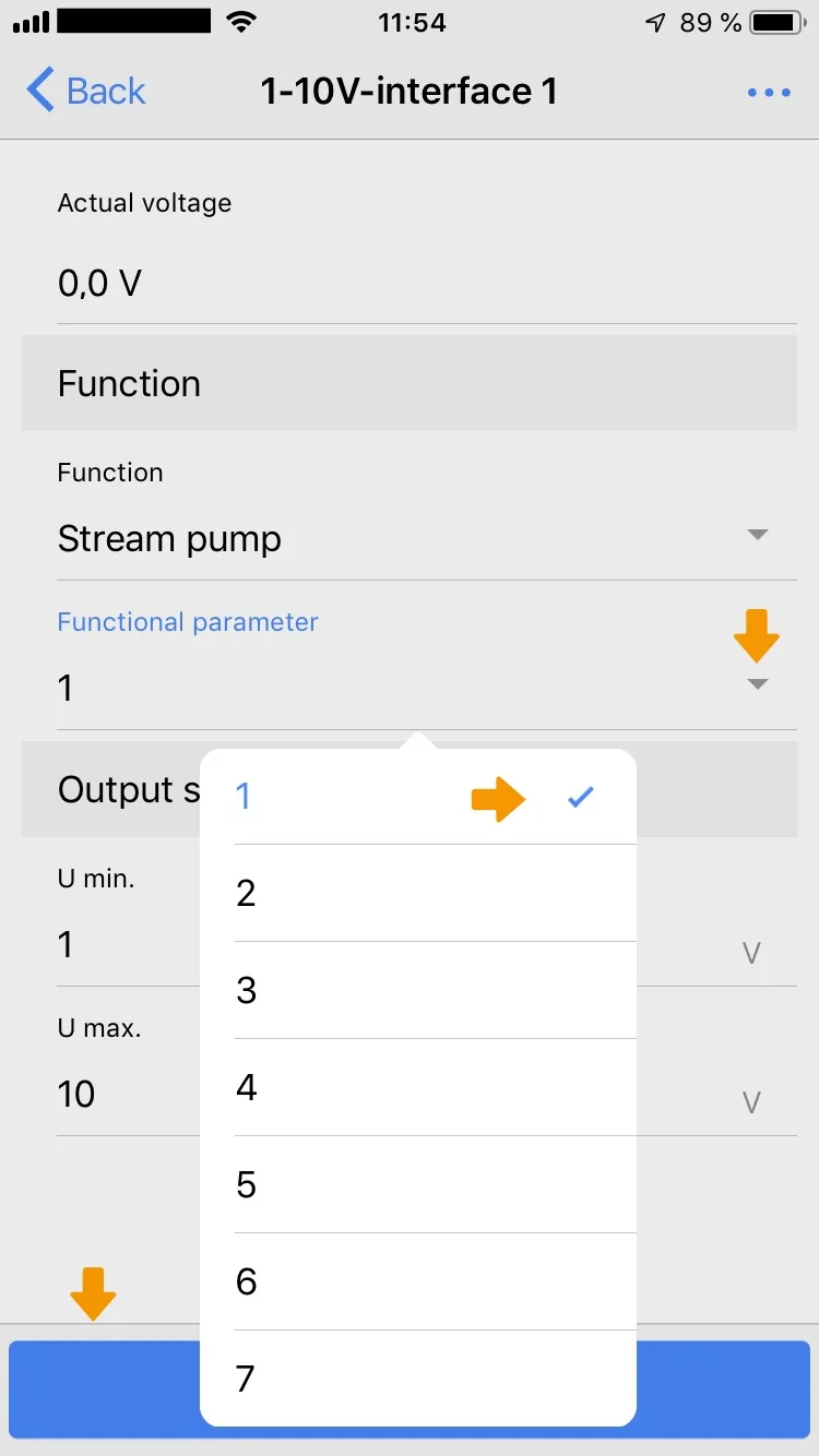
To assign this stream pump to the interface, choose Functional parameter. Then select the pump number that you assigned when setting the pump behaviour (Extras->Stream group XY).
Save the entries.
Configure 1-10 V interfaces via GHL Control Center
GCC
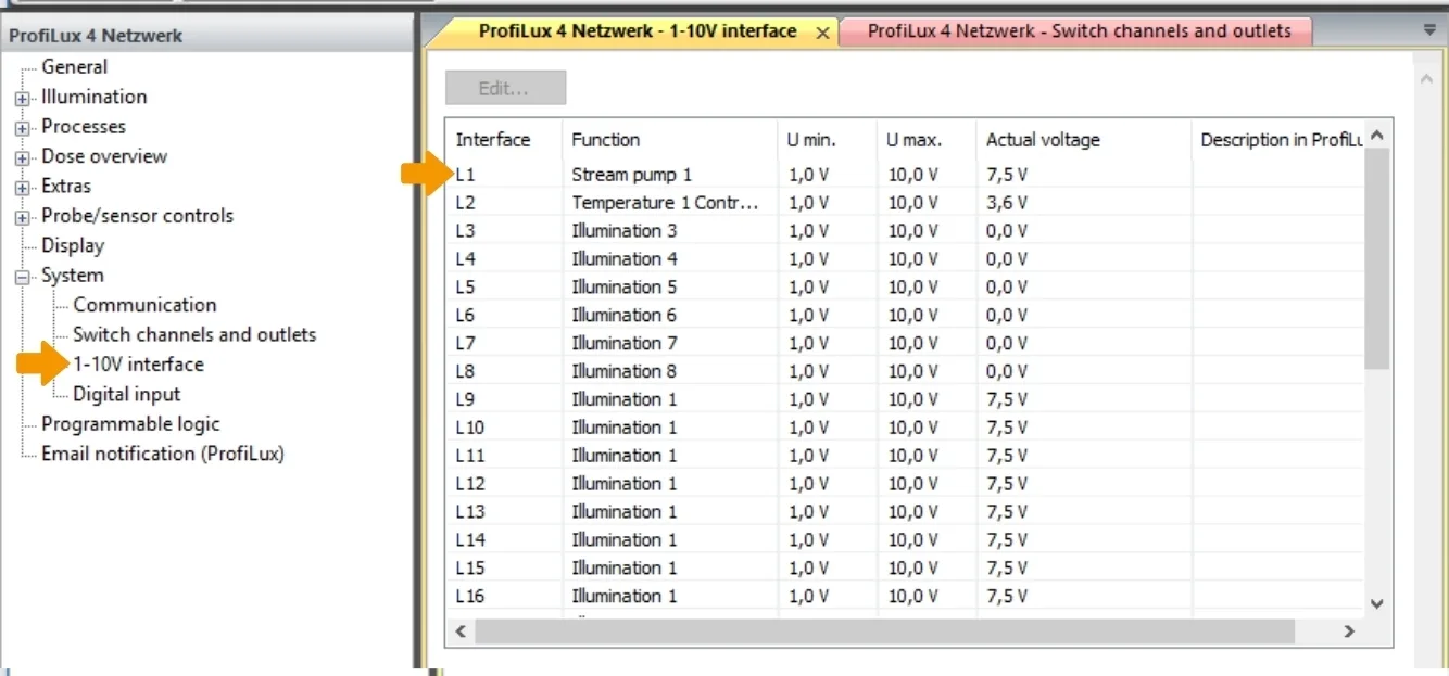
Select System -> 1-10V interface.
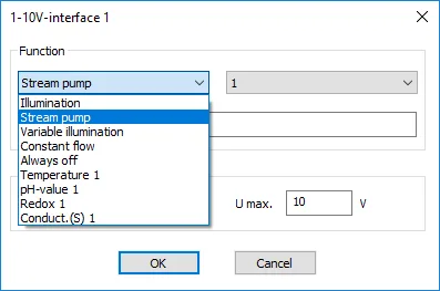
With a double click on any interface you can edit it in a separate window.
Select the function that you want to assign to the interface.
The Stream pump function has been assigned to interface 1.
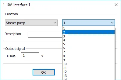
Then assign the interface to the respective stream pump programmed under Extras-> Stream group XY.
How stream groups are formed can be found here:
Connect the pump to the 1-10 V interface L1.
Proceed in the same way with other 1-10 V interfaces.
Functions overview of the 1-10 V interfaces
| Illumination | Then select the Number of the illumination.
Here the dimmable lamps are then connected – e.g. with dimmable ballasts or ProfiLux Moon. This makes it possible to assign any 1-10 V interface to any lighting. |
| Current pump | Then select the Number of the pump.
This interface is then used by the current simulation. |
| Always off | This interface has no function. |
| Variable Illumination | Then select the Number of the variable illumination.
Herewith you can assign a Variable Illumination (siehe auch unter Illumination ->Variable Illumination) to this interface. |
| Constant flow | Then select the Number of a flow sensor.
With this function this interface is able to control a variable-speed pump in order to obtain a constant flow, see also Flow. |
Assignment of 1-10 V interfaces to control loops
A 1-10 V interface can also be assigned to a control loop. Select one of the existing controllers (sensors), for example:
- Temperature 1
- pH 1
- Redox 1
- Conductance (S) 1
The selected controller then outputs a voltage proportional to the control difference (= deviation from setpoint to actual value) on this interface.
If the temperature of the water exceeds the set temperature, a voltage proportional to the temperature control difference is put out.
To put it simply: The warmer, the more voltage.
This makes it possible to control an adjustable cooler – e.g. our PropellerBreeze with control electronics PropellerControl – and to operate it as quietly as possible.
GHL Connect App
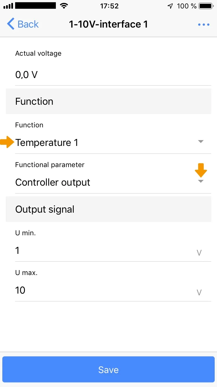
Select Function -> Temperature1 and set Function parameters to Controller Output.
Save the entries.
GCC
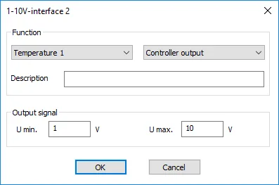
Temperature 1 -> Set controller output
Adaptation of the output signal
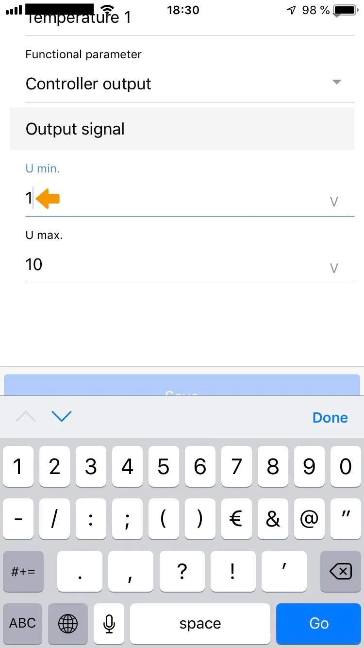
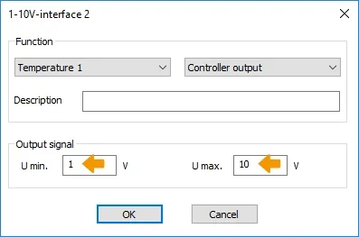
As a rule, the voltage range is 1 V to 10 V, as the name of the interface already indicates. However, the minimum and maximum voltage of this interface can be changed.
It may be necessary to set the minimum voltage (at 1%) (possible range: 0 V to 4 V).
GHL Connect App
GCC
This can be for the following reasons:
- The stream pump stops, although the set flow speed is> = 1%.
- Not all fuorescent tubes are equally well suited for dimming. The fuorescent tube manufacturer can tell you more about the dimming suitability. Most problems are in the lower dimming range (up to approx. 10%). Here it can happen that the fuorescent tube simply shuts off after a certain time (usually a few minutes). Solution: Increase Minimum voltage.
- Not all dimmable electronic ballasts behave the same way. The lower dimming position should normally be achieved with a control voltage of 1V, full brightness at 10V. We have observed that the brightness of some ECGs does not change any further with a control voltage below 1.5V, with other ECGs the dimmable range goes up to approx. 0.8V.
The maximum voltage (at 100%) is adjustable between 4.5V and 10V, e.g. to solve the following problems:
- The flow pump operates with full power already at 8 V.
- For some dimmable electronic ballasts no further brightness change is visible between 9.5 V and 10 V.
- The moonlight is too bright at 10V.
To achieve an optimal dimming curve you can test the following in the menu Manual Illumination:
- Lower dimming values: Noticable brightness change or shut off
- Upper dimming values: Noticable brightness change.
If necessary, the Minimal and Maximal voltage have to be changed and tested again.
Program devices on 1-10 V interfaces
You also have the option to program certain devices that are connected to a 1-10 V interface directly.
For this, the expert mode must be activated in GHL Connect (App Settings) as well as in GCC (View-> Expert Mode).
GHL Connect App
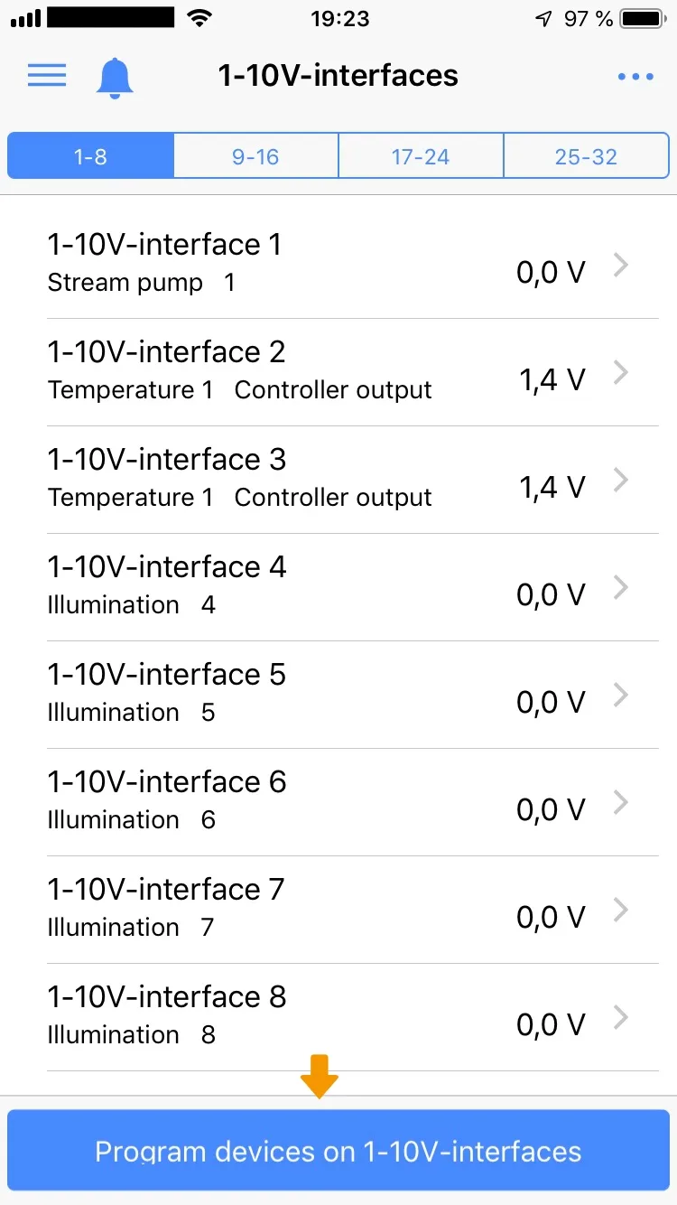
Press Program devices on 1-10V-interfaces.
If the button doesn’t show activate Expert mode in the App settings.
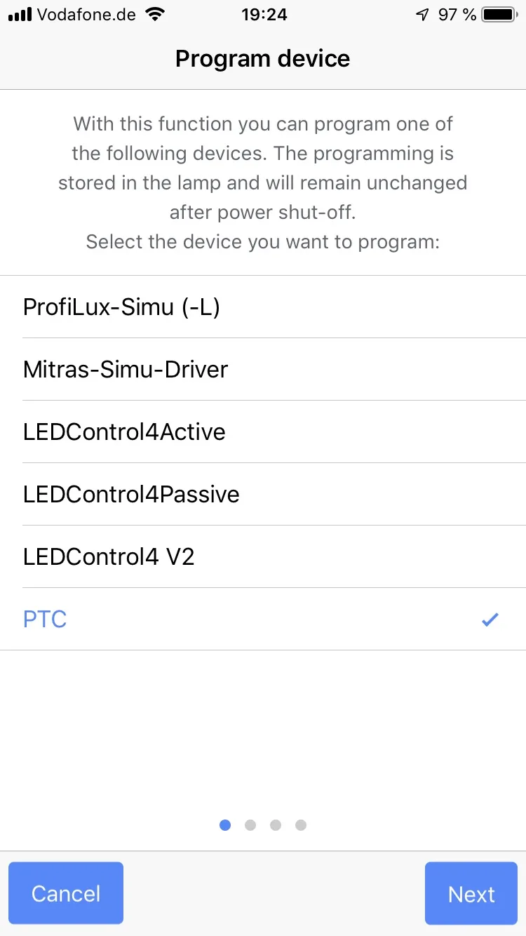
Select one of the devices (here for example PTC).
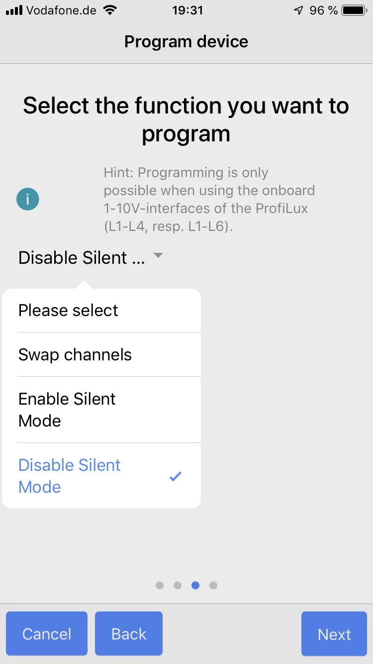
Select the Function you want to program, press Next and finish programming with Done.
GCC
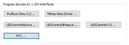
Select one of the devices via the button (here for example PTC).
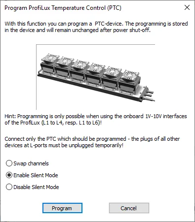
Select the desired changes and press “Program” to save.