About Maintenance mode delays
When a Maintenance mode is activated, the specified Powerbar sockets will react according to how you configured your maintenance settings. For example, when you activate a Maintenance mode, if you normally have your return pump and skimmer turn OFF this results in the water level in your sump rising above the normal level.
At the end of this maintenance, the assigned outlets will immediately turn ON …
While this may be OK for equipment like your return pump, media reactor feed pumps and UV, you don’t want your skimmer to turn ON immediately otherwise the high water level in your sump will cause the skimmer cup to overflow!
The solution to this is to create a maintenance mode delay and assign that delay to the skimmer and any other equipment which you want affected.
To create this delay, you will use Programmable Logic!
Preliminary step: Setup the Maintenance mode function
Before you proceed with the steps below, you must first setup your Maintenance mode function.
If you are not sure how to do this, click here for the step-by-step instructions.
Create the Maintenance mode delay
- Press the Menu icon and select Programmable Logic
- Select an unused Gate


3. Set the function to Delayed Off

4. Set the Input to Maintenance, then specify which maintenance number to use

5. Specify the length of the delay (1s – 16,599s), then press SAVE

You have now created a Programmable Logic function which adds a Delay OFF feature to your Maintenance mode. The next step will be to create a 2nd PL function so you can combine this delay with another function. This “other” function can be the original function you had assigned to the Powerbar socket.
Combine Maintenance delay with another function
- Press the back arrow and select another unused Gate

2. Set the function to AND

3. In the Input 1 section, select the function you want to combine with the maintenance delay.
For example, if you currently have your skimmer set to react to a feed pause, select Filter and choose the feed pause number you had originally assigned.
If you do not have any function assigned to the outlet powering the skimmer, select Always On.

4. Set Input 2 to Programmable Logic and select the PL gate number you used when you created the 1st PL function (Maintenance delay). Invert this function as shown.
For example, if you created the Maintenance delay on Gate # 1, select Programmable Logic 1.
5. Press SAVE

You have now combined your Maintenance delay with your original function. Now it’s time to take this combined PL function and assign it to the Powerbar outlet you want delayed.
Assign PL function (Combined Maint. Delay)
The steps provided below can be used for the following scenarios:
- Skimmer pump is physically connected to a socket on your Powerbar.
- Skimmer pump is controlled via 1-10V.
1. Press the back arrow, press the Menu icon, select Switch channels
2. Select the Powerbar socket that you want reacting to this maintenance delay
If you have the skimmer pump physically connected to a Powerbar socket, choose the switch channel number where you have it plugged into.
If your skimmer pump is NOT physically connected to a PB socket, but is controlled via 1-10V, choose a switch channel that is not assigned to a physical outlet.
- Example: You have a Powerbar-6E assigned to switch channels 1-6. Choose switch channel #7.
3. Type-in a description
4. Set the function to Programmable Logic and select the gate number you used when you created the 2nd PL functionFor example, if you created the Maintenance delay on Gate # 1 and combined it with your original function on Gate # 2, select Programmable Logic 2 .
Why?
Because PL # 2 contains the combination of your delay and original function.
5. Press SAVE


You have now assigned this PL function to your Powerbar socket. Since this PL function contains the combination of your maintenance delay AND original function, the ProfiLux will control the Powerbar socket according to the original function.
When the Maintenance mode is activated, the assigned socket will react accordingly. After this maintenance ends, the PL will delay the reaction by the length you specified.
Assign PL function: Continued (1-10V / Versia control only)
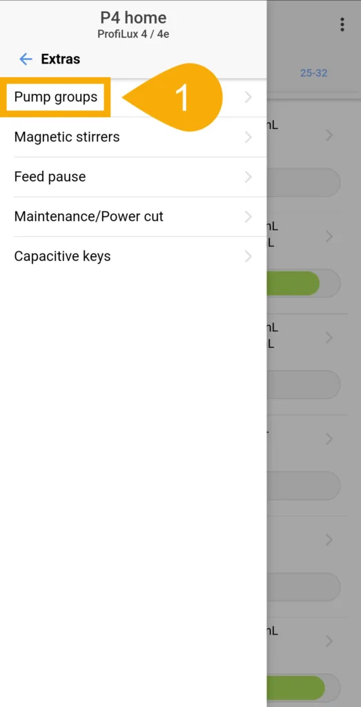
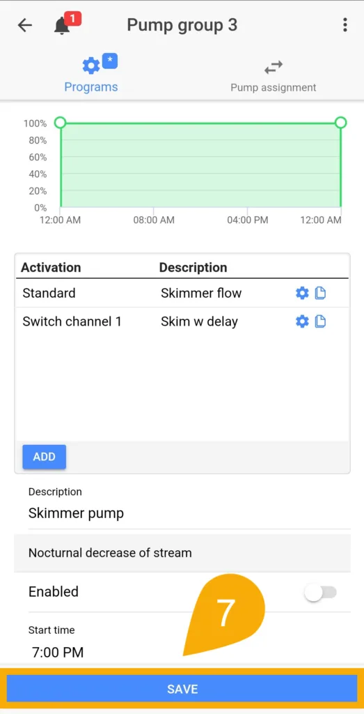
1. Press the Menu icon, select Extras, select Pump groups.
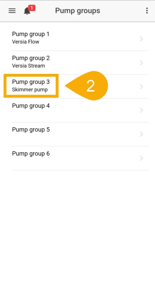
2. Select the pump group where the skimmer pump is assigned.
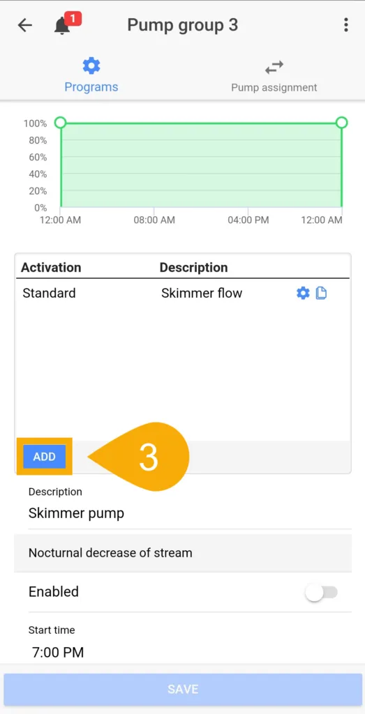
3. Press ADD to create a new program.
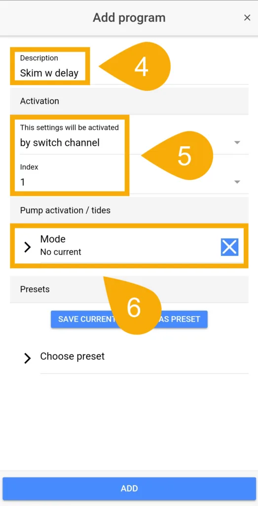
4. Type-in a description.
5. Set the activation to By switch channel and choose the SwCh. number where you assigned your PL function.
6. Set the mode to No current and press ADD.
7. Press SAVE
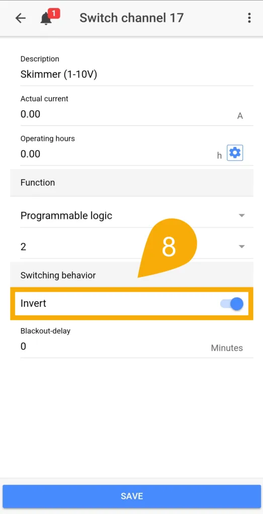
8. Go back to the Switch channels page, choose the outlet where you assigned your PL function, set it to INVERT and save settings.
If at anytime you choose to manually cancel an active Maintenance mode, please note the assigned sockets will still react according to the delay you configured.
For example, if you have a delay of 60 seconds and you manually cancel the maintenance prematurely, the assigned Powerbar socket will resume normal operation AFTER this 60 second delay.